[continues from 4.1.4]
The misalignments between the spacecraft axes XYZ and the detector axes
of each MECS unit xyz can be defined by three angles as follows :
- the spacecraft axes are defined with the Z axis being the NFI pointing
axis, the Y axis being parallel to the solar array, and the X
perpendicular to it, as shown in the
paylod accomodation figure.
- the detector xy mechanical axes are defined by its mechanical mount and
are parallel to the strongback axes and to the
detector electronic axes (i.e. linearised pixel
coordinates)
- the detector z axis completes the triad, and is the axis along the
gas cell and mirror unit
axis. The DU and MU mounting is solidal because of the carbon fiber envelope,
and the misalignments are due to its mounting on the spacecraft optical bench.
- the first angle alpha corresponds to a rotation around the Z axis
(rotations must be applied in this order)
- the second angle beta corresponds to a rotation around the y' axis
- the third angle gamma corresponds to a rotation around the x" axis
- the effect of the three rotations is shown in fig. 4.1.5-I
- the mechanical orientation of the three MECS detectors is such that unit M3 xy
axes are grossly parallel w.r.t. the spacecraft XY axes, while unit M1 and M2
axes are flipped (see fig. 4.1.5-II)
![[definition of misalignment angles]](figrot.gif)
Fig. 4.1.5-I : each panel shows the rotation from the thicker axis
system to the thinner one. The first three panels give the individual rotations described
above, while the last one gives the overall misalignments. The orientation and rotation
relative magnitude corresponds to unit M3, but rotation angles are exaggerated by a
factor 100
The relevant coefficients have been calibrated from raster scan observations of
a given celestial sources at known pointings. For all practical applications there is
no significant rotation (within a couple of degrees) around the Z axis, hence alpha has been fixed
to 0 ° for unit M3 or 180 ° for unit M1 and M2 (to give the same orientation as
the spacecraft axes), while angle beta corresponds to a shift of about 10 arcmin
along the x axis for all detectors, and gamma is smaller (between half
and 2.5 arcmin) with uncertainties of about a quarter of arcmin.
![[MECS unit orientation]](orient.gif)
Fig. 4.1.5-II : orientation of MECS units with respect to the
spacecraft XY axes
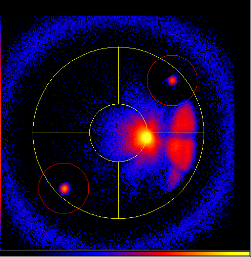
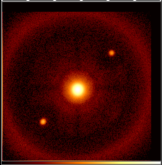
The effect of this is that if the satellite is pointed with its Z axis on the
target, the latter will be positioned behind the strongback. This is visible in the
first light pointing.
The pointing strategy takes account of this, and compensates, placing the source close
to the MECS centre, as in the
second light pointing.
The coefficients are stored in files
m{1,2,3}.misalignment
and are used by software for
conversion
between image and sky coordinates.
The transmission of the
plasma suppression grid,
taug, is
a hardcoded scalar (energy-independent) value of
FILT1=0.921
.
sax.iasf-milano.inaf.it/Sax/Mecs/calib3.html
:: original creation 2002 Sep 04 16:29:23 CEST ::
last edit 2002 Sep 04 16:29:23 CEST